C16 ROM Expansion
-
This is a modification I made to a Commodore 16 motherboard during the summer of 1998. The C16 was basically a stripped down version of another Commodore computer, the Plus/4. The C16 had only 16K RAM compared to the Plus/4’s 64K. The Plus/4 had a total of four 16K ROMs, two for the KERNAL and BASIC and two for its special productivity software. The C16 had only two of these ROMs, the KERNAL and BASIC. Finally, the Plus/4 also had a serial port based on the 6551 ACIA. There was no serial port on the C16.
I decided to expand my C16 because although my Plus/4 had more features, the C16 came in a larger C64-style case with a better keyboard. The first step in expanding my C16 was increasing the memory to 64K. George Hug was nice enough to send me some schematics that he had hand-drawn of the computer and included instructions on how to perform the upgrade. This required replacing two RAM chips, cutting two traces, and adding two additional address wires. The memory upgrade was a popular modification. It is not readily apparent from my photo because I did this work on the bottom side of the board.
After performing the RAM upgrade, I wanted to also put the Plus/4’s productivity software ROMs into my C16. The main problem was that there were only two sockets for the four ROMs. To solve this problem, I burned a single 32K EPROM with the contents of the two original 16K ROMs. I then burned a second 32K EPROM with the two 16K productivity software ROMs from the Plus/4. To make the computer recognize the new EPROMs, I constructed a daughterboard that modified computer’s existing address decoding.
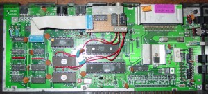
I had intended on building a printed circuit board version of this project, however since I just thought up the idea and didn’t know of anyone who had done it, I handwired it to see if it would work. This is what you see above. Someday I’ll probably build a PCB for it, but if I do I’ll put some other goodies on it as well.
I desoldered the 74LS139 from the motherboard installed a socket installed in its place. The ribbon cable plugs into it and the the ‘139 now resides on the daughterboard. The daughterboard, located on top of the RF modulator, uses two additional chips to complete the address decoding. The small board is wired with point-to-point soldering and is mounted to the top of the modulator with a single piece of double-sided tape.
The original KERNAL and BASIC ROMs are removed and no longer used. These two 16K ROMs are burned into a single 32K EPROM. The 3+1 productivity software, also on two 16K ROMs, are burned into another 32K EPROM. On each EPROM, chip select and the highest address line are bent up ninety degrees. This is because the C16 motherboard is not modified under the ROM sockets; this is a plug-in upgrade (except for socketing the ‘139). The EPROMs are installed in the sockets and four wires connect the lines back to the daughterboard.

